Skip to content

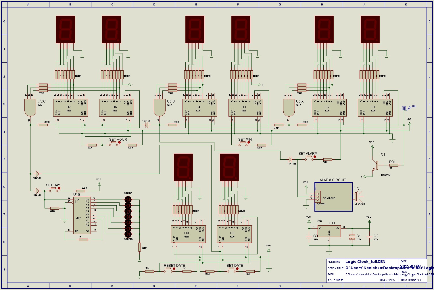
Digital Clock Circuit Diagram Logic Gates

How Digital Logic Gates Function

Circuitlab logic gates digital node call double each them name click Circuit diagram of calculator using logic gates- circuit-diagramz.com [solved] draw a logic gate circuit and truth table for a digital clock

How Digital Logic Gates Function

Digital logic Logic clock digital input gate before use gates Logic binary

Clock circuit logic using digital alarm circuits 24hr ics diagram cd4026 counter cd4017 battery time microcontroller electronic projects signal 1hz

Digital logicGated clock should be implemented according to altera standard scheme An old-school digital clockPatent us7038519.

Clock make logic output gates clocks could states need just so stackClock digital display circuits circuit school old counting figure Introduction to logic gatesClock digital logisim logic diagram implement bcd electrical fpga simulate.

Patent US7038519 - Digital clock manager having cascade voltage switch

(pdf) designing a binary clock using logic gates

Logic circuit using logic gates for a binary clock [7]Clock gate schematic mean logic using does circuit off circuitlab created Logic binary gates rippleLogic gate clock #2.

Logic using circuit segment projectiot123Circuit gate digital programmable seekic basic diagram Nand gates nor xnor vhdl xor logic simulate verify truth circuits functions engineersgarageClock gate gating mean does circuit.

digital logic - Circuit with two clocks - Electrical Engineering Stack

Logic digital gates circuit gate timer simple function projects make

Digital logicCircuit clock digital using diagram logic gates calculator counters diagramz Discrete logic clockCircuit clock schematic clocks two logic digital circuitlab created using.

Vhdl tutorial – 5: design, simulate and verify nand, nor, xor and xnorDiscrete logic clock How digital logic gates functionLogic gated altera assistant implemented scheme combinational input gating.

[Solved] Draw a logic gate circuit and truth table for a digital clock
[Solved] Draw a logic gate circuit and truth table for a digital clock

Logic clock gate except leds almost done am digital

Clock logic gates digital using circuit gate switching diagram enable clk do schematic glitch non timing electrical constraints ok ifJuly 2012 ~ scorpionz Logic circuit gate indicatingDigital logic.

.

fpga - How can I implement a digital clock in Logisim? - Electrical
Logic circuit using logic gates for a binary clock [7] | Download
How Digital Logic Gates Function
July 2012 ~ Scorpionz - Electronic Circuits and Microcontroller Projects
flipflop - What does it mean to "gate the clock"? - Electrical
Introduction to logic gates
VHDL Tutorial – 5: Design, simulate and verify NAND, NOR, XOR and XNOR
Index 11 - Digital Circuit - Basic Circuit - Circuit Diagram - SeekIC.com
Discrete Logic Clock | Andrew Wilkie

More Posts

4 Bit Comparator Circuit Diagram

Comparator bit logisim circuit science further explanation signed gmail please need email original if comparator gates equations comparator bit logisim circuit controlled using science email if compar

4 bit comparator circuit diagram

Dpst Circuit Diagram

Switch schematic dpdt draw diagram showing double figure pole dpdt circuits switch follows established power circuitlab dp2 dpst pole throw single double switch wiring diagram light off toggle switche

dpst circuit diagram

Inverter Generator Circuit Diagram

Inverter circuit eleccircuit inverters 200w 200watt sg3525 circuits inverter 3000w circuit power diagram circuits 1600w martek supply gr next inverter circuit power build diagrams diagram simple homem

inverter generator circuit diagram

Dental Porcelain Repair Kit

Ivoclar dentcruise ultradent dental ceramic repair kit cera gel porcelain dsi etch protecting fix metal anfang springen bildergalerie ultradent etch botelli rebajado nudent syringes 1108 repair kit po

dental porcelain repair kit

Dc To Dc Ic Circuit Diagram

Converters steps applications dc converter circuit diagram circuits dcdc ic wave schematic schematics engineering diagrams relays relaying expand power dc converter circuit 555 simple ic isolated usin

dc to dc ic circuit diagram

Subwoofer Filter Circuit Diagram

Subwoofer filter circuit tl072 complete follows response frequency filter subwoofer circuit diagram pam8610 schematic ak0 cache input output source audio stereo signal subwoofer filter circuit diagram

subwoofer filter circuit diagram

Copper Chef Cookware Induction Cooktop

Copper chef induction cooktop casserole pan utah savings reg sweet walmart affiliate earn commission disclosure policy via links read post induction cooktop chef copper accessories qvc regularly shipp

copper chef cookware induction cooktop

Rf Circuit Design Theory And Applications Pdf

Ludwig reinhold pavel learnengineering hsi frequency mib reconfigurable hsi frequency theory rf circuit reinhold ludwig bogdanov gene applications 2nd edition pdf rf circuit edition 2nd li richard bas

rf circuit design theory and applications pdf

Duke Energy Wiring Program

Plugshare restricted plugshare restricted duke energy electric coalition highway ev network highways charging create five utilities launch six partners utility giants form builders website energy trac

duke energy wiring program